Use:
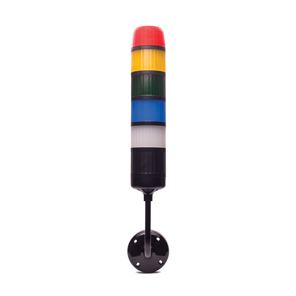
MA-02 automation module is designed to control signal towers of the WS-Ad series via a serial interface.
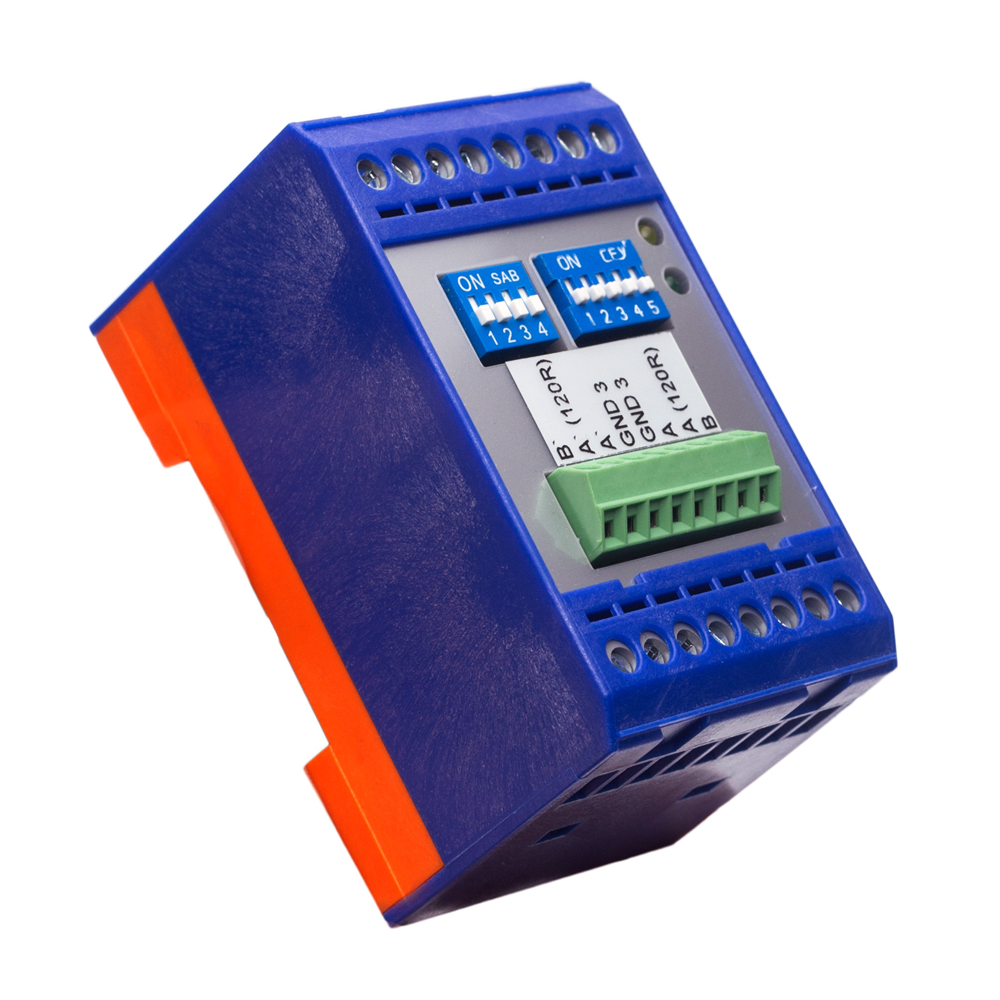
Construction:
The physical layer of the interface is RS-485, a MODBUS RTU transmission protocol. There are two possible modes of the module operation: full-duplex and half-duplex. MA-02 automation module was developed as a universal output device. It permits control over eleven outputs of the OC type (open collector). Thanks to using this module, the user can easily control the operation of the WS-Ad series signal tower directly from the PLC controller level or a PC computer. The RS-485 interface is galvanically isolated from the rest of the device.
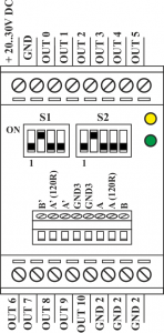
The module casing is made of plastic material. Casing shape design allows for direct mounting of the module on a DIN rail. MA-02 module is equipped with two terminal blocks, consisting of eight tracks each. Connection terminals of the module are located on the front panel of the casing, which facilitates the device wiring.
| Power supply |
20-30 V DC |
| Current consumption at 24V DC |
Inactive outputs <25 mA
Active outputs <60 mA |
| Bound rate |
2,4 kbps – 115,2 kbps |
| Address range |
0 – 31 |
| Transmision protocol |
Modbus RTU |
| Outputs number |
11 |
| Outputs type |
Transistor OC (separated from control circuits) |
| Ingress protection |
IP20 |
| Working temperature range |
-10°C ÷ +55°C |
| Max. cross-section |
2,5 mm2 |
| Weight |
~125 g |
| Dimensions |
45x75x45 mm |
Control:
In the process of communication the device acts as a slave. The device has a built-in, 5-position DIP switch, by means of which it is possible to set an address in a range of one to thirty-one (address selection method is shown in Table 1). If you set all the positions to ON, the device address will be taken from a programmable register. Default register value is set to thirty-two. It is also possible to set ten different data rates depending on the parameters of the bus. Speed selection shall be done using the built-in four-way micro switch, as shown in Table 2.
| Pr.1 |
Pr.2 |
Pr.3 |
Pr.4 |
Pr.5 |
Address |
| 0 |
0 |
0 |
0 |
0 |
1 |
| 1 |
0 |
0 |
0 |
0 |
2 |
| 0 |
1 |
0 |
0 |
0 |
3 |
| 1 |
1 |
0 |
0 |
0 |
4 |
| 0 |
0 |
1 |
0 |
0 |
5 |
| 1 |
0 |
1 |
0 |
0 |
6 |
| … |
| 0 |
1 |
1 |
1 |
1 |
31 |
| 1 |
1 |
1 |
1 |
1 |
Programmable |
Table 1. Setting the device address using the DIP switch S2.
| Pr.1 |
Pr.2 |
Pr.3 |
Pr.4 |
Baud rate [kbps] |
| 0 |
0 |
0 |
0 |
2,4 |
| 1 |
0 |
0 |
0 |
4,8 |
| 0 |
1 |
0 |
0 |
9,6 |
| 1 |
1 |
0 |
0 |
14,4 |
| 0 |
0 |
1 |
0 |
19,2 |
| 1 |
0 |
1 |
0 |
28,8 |
| 0 |
1 |
1 |
0 |
38,4 |
| 1 |
1 |
1 |
0 |
57,6 |
| 0 |
0 |
0 |
1 |
76,8 |
| 1 |
0 |
0 |
1 |
115,2 |
Table 2. Setting the baud rate using the DIP switch S1.
Operation of the module is indicated by LED diodes located on the front panel of the casing. The yellow LED light informs the user of ongoing data transmission, while the green LED informs that the module is being powered.
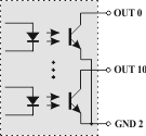
The output circuits are implemented on the basis of opto-isolators in open collector configuration, which provides galvanic isolation of the module outputs.
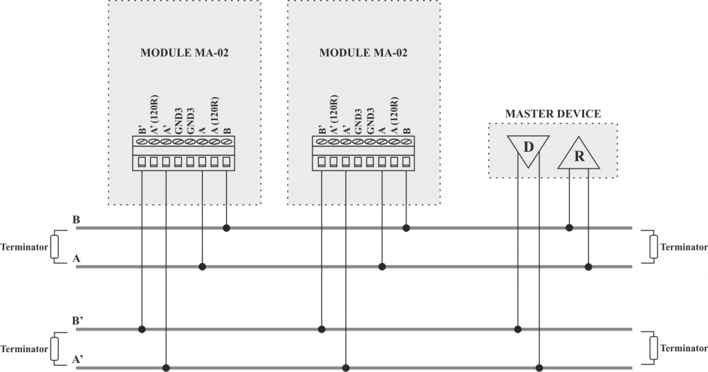
Communication with the module takes place in accordance with the requirements of the MODBUS RTU protocol. The module address on the bus and baud rate can be set via micro-switches S2, S1.Other communication settings are: 1 start bit, 8 data bits, 1 parity bit (EVEN), 1 stop bit. The module acts as an output device, so only some features of the MODBUS RTU protocol are used – see list in Table 3.
Function code
|
Function description
|
| 01H |
Read coils |
| 03H |
Register read |
| 05H |
Write single coil |
| 06H |
Register write |
| OFH |
Write multiple coils |
Table 3. Implemented functions of the MODBUS RTU protocol
To set the output to a LOW state (output activation – shorted to ground), the logical 1 should be entered into the frame responsible for setting the digital output.
After the reading of the states of digital outputs is completed, the device returns a value of 1 for the output that is active (shorted to ground).